1 Introduction
Starting in the winter semester of 2022/2023, I attended the Research Project Telecooperation at TU Darmstadt under the supervision of Prof. Dr. Jan Gugenheimer. In this course I worked on a research project with a focus on human computer interaction and a topic related to emergenCITY.
The vision
The overall vision is a system running on a mobile head mounted display, which is able to analyze its surroundings in
order to predict what might happen. Based on these predictions, it then shows the relevant data to the user, helping him
make better decisions.
One exemplary use case is equipping security officers with such devices. When an officer is overseeing large crowds, the
device could on the one hand predict where panic might break out. Therefore, it could then show the officer where he
needs to intervene in order to prevent the outbreak.
On the other hand, the device could identify possible escape routes, so the officer can make sure they remain accessible
and, in case of an emergency, guide the crowd towards them.
My project
The goal of my project was to build a Unity application for an XR-headset, which can be used to investigate how the device has to present information to its user, so that he can understand it as intuitively and as quickly as possible. The concrete use case we chose was the comparison of different approaches to visualizing how the people around the user are going to behave.
Quick preview: the resulting application
After modeling the environment, where the system is being used, researchers can let user-study participants run a
simulation of how the surrounding people are going to behave. Before starting the actual simulation, the participants
can place sources of fire for the people to run from, as well as obstacles to block their way. During the simulation,
they can observe which paths the fleeing characters are taking. After the simulation, the individual characters can be
rewound to any point along the paths they took, allowing the participants to investigate potential bottlenecks, for
example.
The following video showcases such a simulation in the final version of my application.
Download the apk of my application
The structure of this documentation
Chapter 2 provides information about the hardware I used during this research project. After this, chapter 3 describes the implementation of the application’s basics, like modeling the environment, followed by the implementation of the actual simulation in chapter 4. Chapter 5 concludes this documentation, containing a review of what I have learned throughout this project, and an outlook on potential future work with the application I have built.
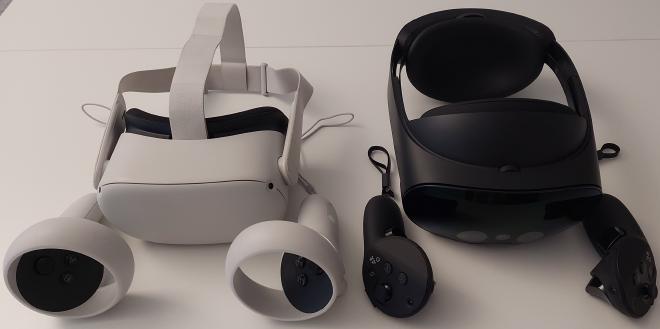
2 Hardware
In the beginning of the research project, I started developing for the Varjo XR-3, a headset with particularly high-quality cameras. However, because of firmware problems rendering the cameras unusable most of the time, I had to switch to a different headset.
With a Meta Quest 2 as a transition device, I later worked with a Meta Quest Pro. While the Quest Pro contains inferior cameras compared to the XR-3, they were sufficient for the purposes of the project. The Quest Pro being a standalone headset with inside-out tracking had the disadvantage of providing less computing power, but it also had the advantage of not requiring a setup including a computer and tracking hardware nearby. The ability to move around freely without the restriction of cables improved the user experience of the application.
3 Foundation
Before I could tend to the actual simulation of the people’s behavior, I had to implement the fundamentals required for such an application. This includes modeling the environment, being able to save and load these models, modeling the persons whose behavior you want to simulate, and different ways to visualize all of this.
3.1 Modeling the environment
For the first approach at modeling the user’s environment, I tested scanning the room before running the application. While trying to use the resulting point cloud to reconstruct a virtual representation of the room, I came to the conclusion that smoothing the model and fixing the holes would have been too much work to be justified by the benefits of this approach.
Instead, I opted for a much simpler approach: manually modeling the environment within the application using cuboids only. The floor could be represented through the ground plane provided by the headset’s tracking. While this approach creates a very simplified model of the environment, it is still sufficient for our simulation needs, as we have a ground plane for characters to walk on, as well as walls and other obstacles represented by cuboids.
In order to allow the user to create obstacles quickly and accurately, I implemented a system where you first place three points on the floor using the controller’s laser pointer. Based on these three points, a rectangle is spawned in, which can then be extruded upwards creating the desired cuboid. Once placed, a cuboid can still be moved and rotated for fine adjustment.
3.2 Saving and loading
With the manual approach to modeling the environment came the need for a save and load system, so you don’t have to recreate the entire geometry every time you start the application. Another reason for such a system was that putting down the Meta Quest for a while and then using it again sometimes causes the Unity application to lose tracking and therefore shift the whole scene.
I ultimately implemented such a system based on a spatial anchor, whose position the user chooses once when saving a modeled environment. Positions and orientations of the objects modeled by the user are then converted to values relative to the anchor’s position and orientation before writing them to a JSON save file. When this save file is loaded later, the headset automatically recognizes the anchor in the room and provides its data to the application. Based on this data, the stored objects can then be recreated in their original positions, aligned with the real world, without requiring the user to redo any modeling or alignment.
The following code snippet shows an example save file (containing a single obstacle only):
| |
3.3 Modeling persons
A future real-world application will require the headset to recognize and track all persons around the user in real-time, for example using computer vision. However, since our focus was to investigate different ways to visualize relevant data to the user, we limited our implementation to letting the user create virtual characters where needed before starting a simulation.
The user first chooses where to create a new character. After this, he can scale the virtual model in order to adjust it to the person being modeled. Once the character was scaled, it can be moved and rotated afterwards, allowing to align it with the actual person’s orientation more closely.
As virtual characters are being rendered on top of the headset’s live video feed, while obstacles are not, they would by default always show on top of everything in the real world. Because of this, the user would be able to see all characters through walls and tables, for example. This would be confusing as well as detrimental to the user’s immersion, so I applied a shader, which added character occlusion to the obstacle geometry.
3.4 Visualization options
As a starting point for the application, I implemented two types of visualizing the characters themselves, as well as three types of traces visualizing the paths traveled by them.
Character visualization
The first type of visualizing the characters is the humanoid visualization, where the characters are represented by an
animated humanoid model (video 1). This type is supposed to closely mimic how an actual walking person would look like.
The second option, the sphere visualization, is a more minimalist and abstract approach, representing characters through
a simple levitating sphere (video 2). The idea behind this was that the humanoid visualization might get too cluttered
and overwhelming for larger numbers of characters. The spheres being much smaller and lacking animations might therefore
provide a clear overview, even with a lot of characters in the environment.
Trace visualization
The first type of trace is the humanoid ghost trace, where the current pose and position of the character are
periodically copied and shown in static humanoid ghosts (video 3). The ghosts’ opacities fade along the trace, with the
ghost closest to the character being the most opaque one, and the one farthest away being the most transparent one.
Next is the sphere ghost trace, where only the position of the character is copied to show ghosts in the form of spheres
(videos 4 and 6). As with the humanoid ghosts, the opacities of the sphere ghosts also fade along the trace.
The final type of trace is the trail, which renders a continuous line in the air following the path traveled by the
character (videos 5 and 7).
4 Simulation
With the fundamentals taken care of, I started building the simulation part of the application.
After modeling environment and persons, the user can place possible destinations for the virtual characters to run
towards. Once this is done, the application can be switched to simulation mode. At this point, the headset can be handed
over to potential user-study participants.
4.1 Basic simulation
In the simulation mode, the participant can manipulate the environment by placing fire sources. When he starts the simulation afterwards, every character will start to run towards one of the predefined destinations. For this, the characters take all fire sources into account to pick the best destination for their starting positions.
The following two videos were recorded with the same virtual environment, characters and destinations. Depending on where a fire source is placed, the characters choose different destinations to run towards. When fire is placed between the characters, they run in opposite directions. However, when the fire source is placed between one of the destinations on one side, and all characters on the other side of it, all characters run in the same direction, towards the destination away from the fire.
Adding obstacles to the simulation
Apart from placing fire sources, the participant also has the option to place additional obstacles into his environment. This allows him, for example, to compare how long it would take the persons to reach emergency exits, depending on where in the room the new arcade game is placed.
4.2 Simulation with rewinding
The final addition to the application was the implementation of the rewinding system.
New rewind trail
Within the simulation mode, while the characters are walking towards their destinations, their positions are recorded at a fixed time interval. Additionally, a new rewind trail is rendered for every character, similar to the existing trail trace, but placed on the floor. The placement on the floor maintains a uniform visualization of all paths, regardless of the characters’ sizes. The white spheres in the trail indicate the recorded positions. (For an actual user-study, you might want to remove the spheres and decrease the time interval.)
Rewinding characters
Once all characters have reached their destination and stopped walking, the participant can access the rewinding system. By pointing at a rewind trail and pressing a button, a character can be selected as the one to be rewound. This will reset him to the point in time, where he passed the part of his rewind trail that is being pointed at. Using a joystick on the controller, the participant can then move the character forward or backward in time. Finally, the character can also be told to replay his walk towards the destination starting from any point in his rewind trail.
Demonstration of the entire simulation mode
The following video showcases a short demo with examples of all the functionality available in the final simulation mode, recorded with humanoid visualization and with no traces apart from the rewind trails.
5 Conclusion
The application I have created during this course serves as a foundation that can be built upon.
One possible direction for this is adding new types of visualizations for the characters and the traces representing
their paths. This would allow the application to be used in user-studies investigating the advantages and disadvantages
of the different types of visualizations.
By comparing a control group without HMDs with participants using the application, one could also examine which kinds of
use cases benefit the most from such a prediction system.
Another direction of extending the application was proposed by Yanni Mei, who is going to add the option to take on the
points of views of the simulated characters at any time. This will allow the users to observe the environment from a
different perspective, for example through the eyes of a very small person as compared to the point of view of a very
tall person.
What I learned during this research project
This project gave me the opportunity to work with a range of exciting XR-/VR-headsets, mainly the Varjo XR-3, the Meta
Quest 2 and the Meta Quest Pro. It was great to be able to try out new technology and to explore both its capabilities
and its limitations.
Building the application also allowed me to improve my Unity-skills when it comes to AR in general and to the frameworks
of the specific HMDs.
Apart from hardware and software, I got a first impression of the research process in human computer interaction through
the meetings with Jan and Yanni.
To be continued
Directly following this research project, I will keep working on the overall project together with Jan and Yanni as part
of the Seminar Telecooperation. The seminar will involve less implementation than the research project and have a bigger
focus on how to write scientific papers.